Logical Network Diagram: Examples, Definition, Symbols \Explained]
Let me give you the basic knowledge of the logical network diagram. Not just that, but we will also tackle how this LND differs from the physical network diagram. Although, both of them fall on the same task, which showcases the connection of your technical devices. Still, both have different purposes of designation and comprehension. Others don't know how this LND works. Still, in your case, after reading this article, you will be able to understand, determine, and utilize it without any hesitation and understand its importance. We feel your excitement about this, so let us start to untie the rope, receive a profound understanding of LND and see the logical vs. physical network diagrams.

- Part 1. What is a Logical Network Diagram (LND)?
- Part 2. The Benefits of Logical Network Diagram
- Part 3. Logical Network Diagram VS. Physical Network Diagram
- Part 4. Logical Network Diagram Examples
- Part 5. How to Make a Logical Network Diagram
- Part 6. FAQs About Logical Network Diagram
Part 1. What is a Logical Network Diagram (LND)?
The LND is the type of network diagram that showcases the elements or components connected within the network. Such components include computers, fax machines, printers, firewalls, servers, etc. How one is connected to the other is represented by the logical network topology diagram, for it tells how the transmission happens within these instruments in a network logically. On the other hand, the network diagram is the outline that shows the network itself to the technical team, such as the IT admin and cybersecurity. In addition, it is where those mentioned teams detect malicious attacks and errors happening in the network.
Elements of the LND
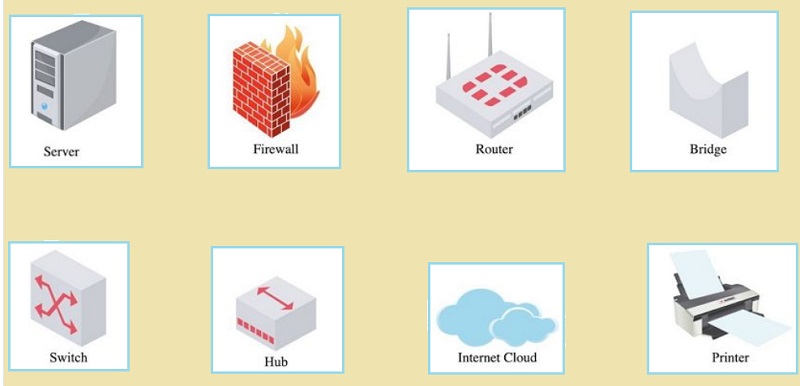
1. Symbols - the LND uses symbols that will represent the types of equipment included in the network. Below are the usual symbols used to present the usual instruments such as the bridge, printer, firewall, router, etc., in a simple logical network diagram.
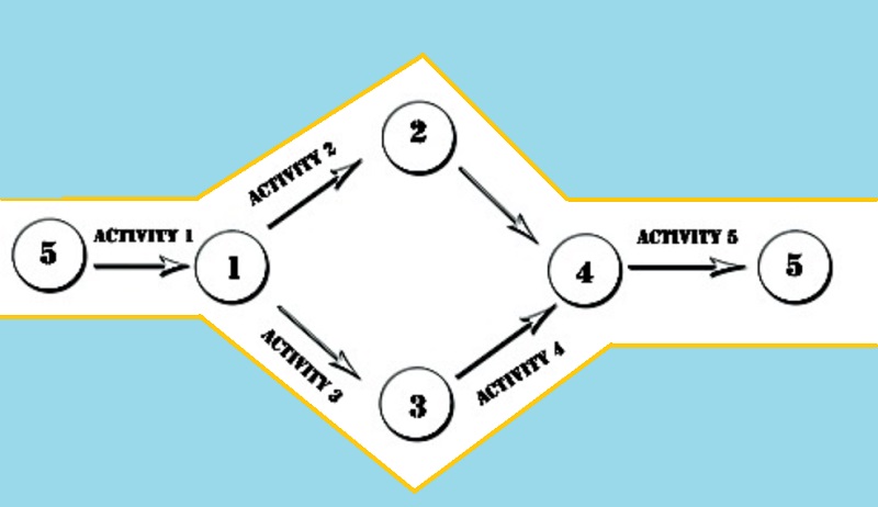
2. Events - The events in the LND always appear in circles. This event means the accomplishment of the activity and also means a new activity will start. There are three classifications of events, the merge event, the burst event, and the merge and burst event.
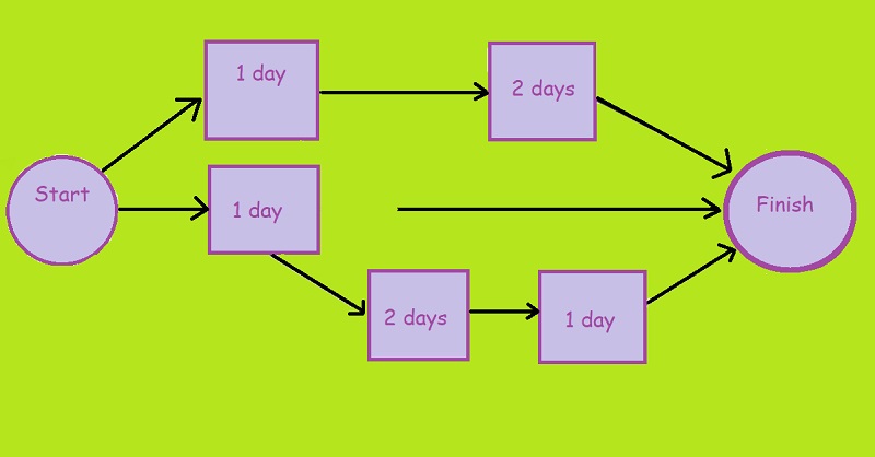
3. Sequencing - is the element of LND that shows the association of the activities in one another.
Part 2. The Benefits of Logical Network Diagram
The following shows how a network diagram, especially the logical one, is being beneficial to the network users:
It secures the network from cyber-attacks. We know how these cyber-attacks affect the profit of the company. Well, yes, this technical affliction causes billions of losses for a company, and it can be avoided by monitoring such afflictions by using the logical network diagram.
It resolves technical errors. It can easily detect errors if the technical department monitors an LND. Bugs and data leaks are unfortunate and uncontrollable events within the network system. How could an IT start troubleshooting those troubles without knowing where they leaked? And that’s the importance of LND.
It organizes the components very well. The LND stands to organize and showcase if there are malfunctioning components.
Part 3. Logical Network Diagram VS. Physical Network Diagram
There are the differences between the logical and physical network diagrams. Some may distinguish their differences as their names suggest, but there are more than that. For this reason, let us see the difference between logical and physical network diagrams with the information below.
| Physical Network Diagram | Logical Network Diagram |
| The physical network diagram shows what they call the bird’s eye view. It physically shows the real cables, LAN connectors, and the devices in the network. Moreover, this type of network diagram shows the hardware components such as the ports, cables, servers, etc. | The Logical type of network diagram shows the behavior of the data when they flow between the devices. In other words, it is the analytical flow of the network. |
Part 4. Logical Network Diagram Examples
This part will see the three LND samples that can help you visualize and grasp.
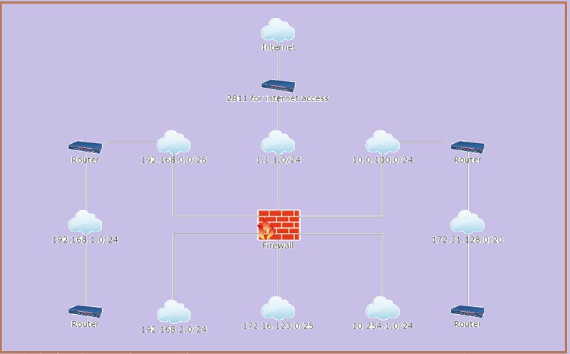
1. Example of an LND with Firewall
It is one of the primary logical network diagram examples. As it is shown in the image below, you will see how a firewall secures all the router devices connected to it.
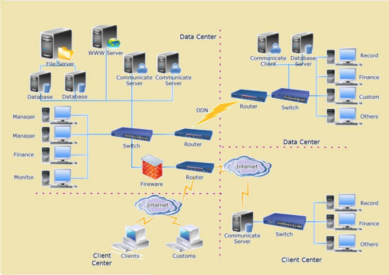
2. Example of LND for Data Center
The photo below will depict the network diagram of a data center. As you can see, it also shows the connection between the data center and client center by the internet and devices they use.
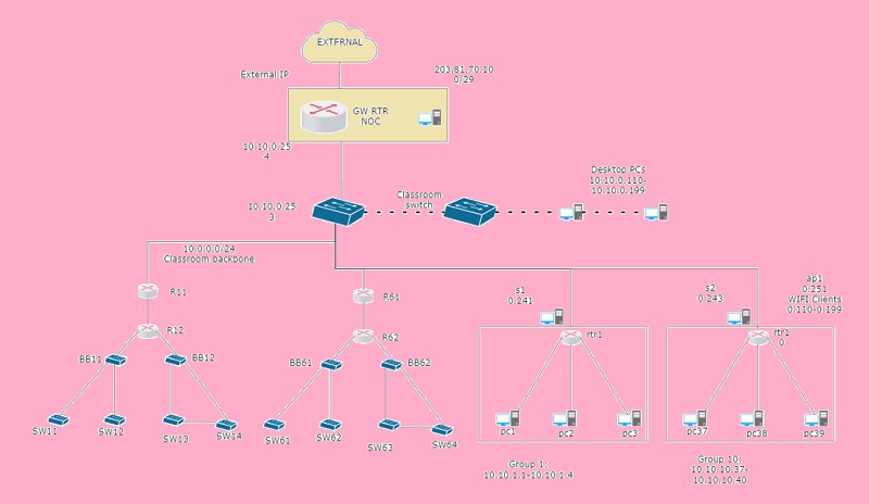
3. Example of a Homeroom Setup
This example is quite helpful for the technical team of a school. It is shown how the groups correlated until they reached the external and vice versa.
Part 5. How to Make a Logical Network Diagram
You have been fed up with the profound meaning and examples of this matter. So, now let us learn how to draw a logical network diagram with the help of the phenomenal mind mapping tool today. The MindOnMap is the leading web-based tool that efficiently helps users with their mind mapping, charting, and diagraming tasks. Since LND is made with symbols and peripherals, MindOnMap is the perfect tool you need to use. It has beautiful icons, shapes, and colors that will bring authenticity to your LND. In addition, it supports any images you want to put onto your diagram, so adding up the symbols that the network diagram needs will not be a hassle.
What’s more? This web-based tool is easily accessible with any device you use as long as it has the internet. Not to mention, it's a comfortable way for the users to share their logical network topology diagram to collaborate with their colleagues. And how comfortable it is to print your diagram using various formats. So, without further adieu, let’s glimpse the detailed steps below.
Create an Account
Initially, visit the official website of MindOnMap, and click the Create Online button to direct you in creating an account. When you get there, log in using your email account. You also can access MindOnMap for desktop by clicking Free Download.
Secure Download
Secure Download

Begin Diagraming
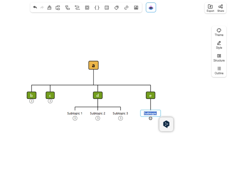
Proceed to create your diagram when you hit the New tab, selecting a template. On the actual canvas, start expanding your diagram by adding nodes when you click the TAB key and customizing them according to your logical network diagram.
Add up the Images/Symbols
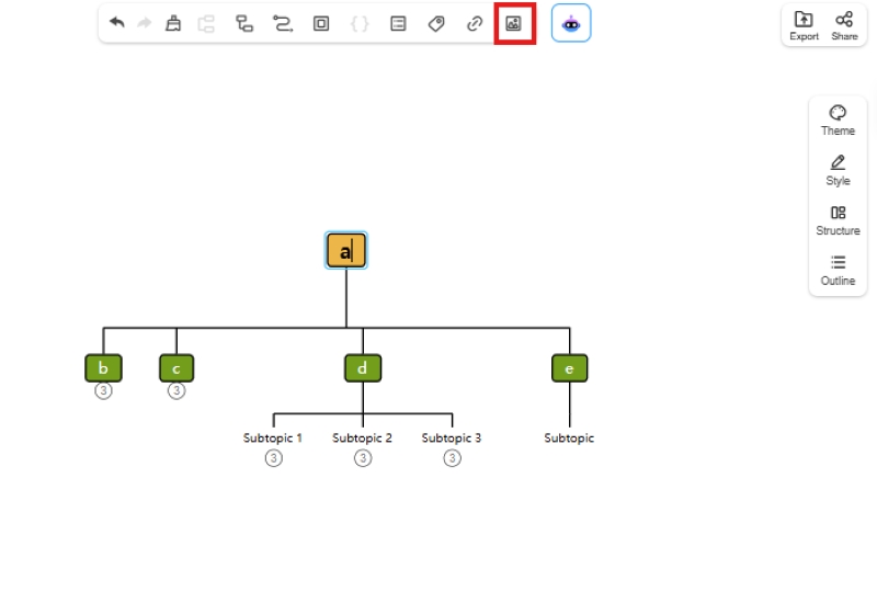
To add images onto your diagram, click the node and hit on the Image button from the ribbons. Then, upload the photo from your device.
Touch with Colors
The background will always make your diagram look professional. So, let us navigate on the Menu Bar, then access the Theme and Background.
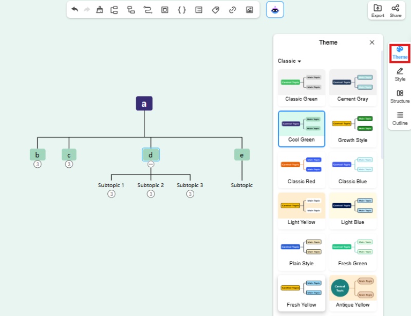
Touch with Colors
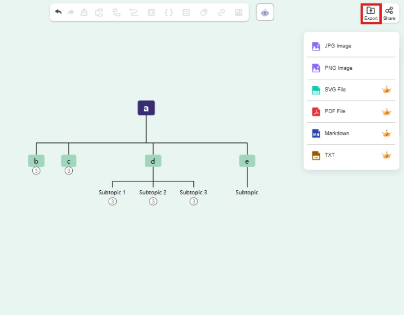
To save the diagram, you can just hit the CTRL+S keys, and it will save your work on your account along with your mind maps. Otherwise, if you want to keep it to your device, hit the Export button, and choose a format for your logical network diagram, then it will be automatically downloaded.
Further Reading
Part 6. FAQs About Logical Network Diagram
What kind of logical topology is Ethernet?
Ethernet is on a logical bus topology where all mediums and connectors are being exposed via Mac address.
What are the drawbacks of the network diagram?
A network diagram consumes time, for you will need the exact estimation, details, and other related technical mediums. In addition, it requires technical knowledge to do it.
What is the common LND used in the small company?
The firewall LND is the typical network diagram that fits new companies. It is a good start, especially if the company uses minimal devices or mediums for the network.
Conclusion
All the basic explanations you need to learn about the logical network diagram are here. At least, you know now how it will be a big help for a company that runs with network technicalities such as the small BPO companies. Take time to follow the previous guidelines, and make it easier with the help of MindOnMap.


